Natural Stone Cutting: From CAD Plan to CNC Machine
Every CNC machine ships with nesting software. These tools place parts efficiently on a slab. But natural stone projects are far more layered and demanding. They require answers to entirely different questions: How does an architecture project move from design concept through material sourcing, range review, and architect sign-off to finished cut pieces? Between the nesting software at the cutting stage and the architect's plan at the start, there's a gap that most fabrication shops fill with printouts, spreadsheets, and phone calls. This article explains why nesting alone isn't enough — and how a digital workflow covers the entire process.
Why Nesting Software Alone Falls Short
The software bundled with a CNC machine solves one specific problem: placing parts optimally on a slab. Minimizing waste. Generating machine code. Some of these tools even handle Veining matching across a single slab. That works — for exactly that one step.
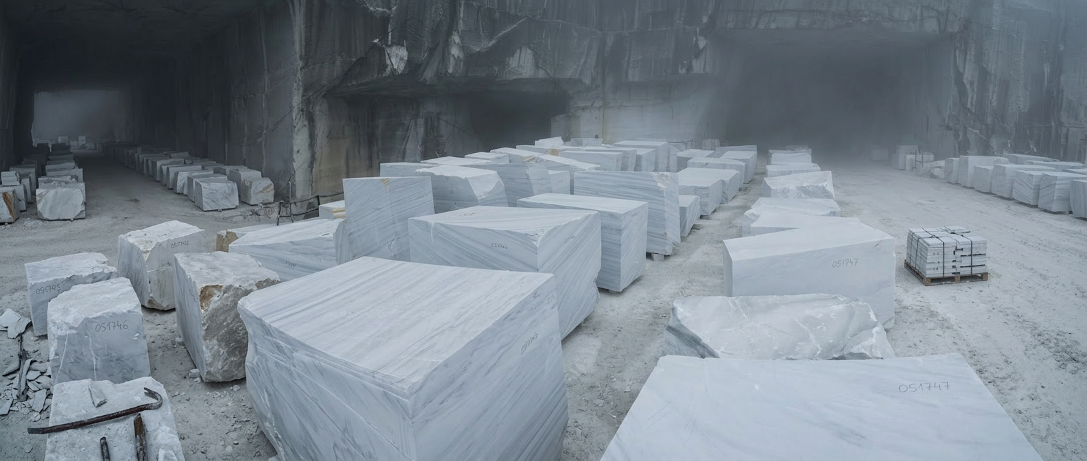
But a natural stone project doesn't start at the cut. It begins months earlier, when an architect designs wall elevations, floor layouts, or facade plans. Not as cutting lists, but as a design concept with material specifications. A contractor takes over sourcing: selecting quarries, purchasing blocks, having them sliced. The plans arrive at the stone fabrication shop — along with the specification of which visual appearance the architect has approved. What falls within range and what doesn't.
Before a single slab is cut, a process takes place that no nesting software covers: range reviews, where project stakeholders travel to the quarry to inspect blocks in person and decide which material matches the approved visual appearance. Inspections where cut material is checked against the appearance the architect expects and either approved or rejected. Back-and-forth on dimensions, edge finishing, surface quality. On a current facade project in Canada — 4,000 square feet of green quartzite from Brazil — exactly this kind of end-to-end decision chain was the core reason for moving to digital planning: giving the end client full traceability from material selection through sign-off to final cut.
Without digital project planning, this process runs on printouts, site visits, comparisons, and spreadsheets exchanged by email. On physical Dry Layout sessions in the warehouse, where slabs are repositioned to optimize the visual result — all at a significant time cost that directly drives up project expenses.
Park Industries estimates that fabrication shops without digital planning lose up to 40 percent of their material as waste. The cause is rarely the nesting itself — it's the missing context that precedes it: Which slab needs to go into which project? Which areas has the architect approved? Which fabrication steps are specified? Nesting software answers "How do I place parts on this slab?" — but not "Which slab, for which project, with which approval?"
Three Phases — From DXF to Cut
Import the Plan and Assign Material
Architect drawings are uploaded as DXF files and can be updated at any point when plans change. Closed polygons are detected as cut pieces. The numbering embedded in the drawing is assigned to each piece as a permanent ID that travels with the part all the way to installation on site. DXF layers define additional fabrication steps: edge finishing, mitre cuts at various angles, radii, anchor slots, drill holes, and more. CNC machines with tool changers can execute these steps in sequence — the part moves from the cutting table to quality control without any additional handling.
Blend, Review, Approve
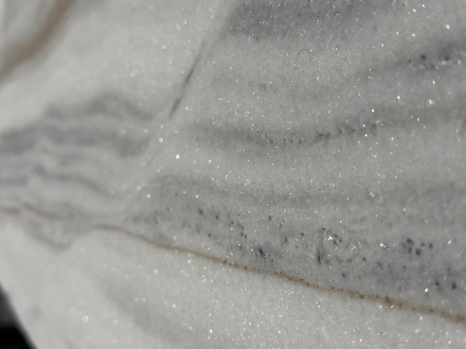
This is where standard nesting tools reach their limit. Real, calibrated slab photos are digitally placed onto the plans — across projects, according to the design and range requirements of each job. The visual appearance is optimized on screen before a single slab is cut. The architect, designer, or project lead reviews the result and releases it for production. A freeze mechanism timestamps the approved layout: who decided what and when is on record. Once approved, it cannot be accidentally changed. Project stakeholders can see which areas meet the range requirements and which don't — and can correct or approve accordingly. This step does not exist in any standard nesting tool.
Export Cutting Tickets and Return Remnants to Inventory
A DXF cutting ticket is automatically generated for each natural stone slab: geometry, edge finishing, drill holes, anchor slots — everything the CNC cutting machine needs. No manual dimension transfer. Through projects, compatibility has been verified across a wide range of machine manufacturers. Beyond the cut itself, larger slab remnants can be returned to inventory. The system flags this optimization step automatically before production approval. Accepted remnants are immediately assigned a new ID and barcode, along with a photo, dimensions, and provenance in the system. The next project can find and use these pieces.
Layer Encoding: The Language Between CAD and CNC
Layer keys make it straightforward to define and record fabrication steps within a project. There are standard layers for common operations — polished edges, mitres, drill holes, anchor slots — as well as open layers for special or project-specific steps. The drafting effort is minimal: one polygon on the correct layer is all it takes to define a fabrication step. The system also instantly calculates required quantities: square meters of cut pieces, linear meters of edge finishing, number of drill holes — everything needed to track project costs. This can be automated using a company-specific price table: when new or revised plans are uploaded, cost changes become visible immediately. The timber industry has operated on this standard for years. In natural stone, it's time to do the same.
Inside DDL: From DXF Import to CNC Export
DDL imports DXF files and automatically detects cut pieces from closed polygons. The embedded numbering is assigned as a permanent ID that travels with every part to the job site. The Blending tool places real, calibrated slab photos precisely onto the cut pieces in the plan and displays each section individually — so the Veining per part can be reviewed and the visual result refined. In parallel, the nesting per slab is shown as an overview above the blending — a single click switches to the slab view to see the nesting live and adjust it manually or, in the future, with AI assistance. A freeze mechanism timestamps the approved layout: who decided what and when is fully documented. Cutting Tickets are exported as unique DXF files per natural stone slab for the CNC cutting machine — including edge finishing, mitres, drill holes, and anchor slots from the layer keys. Slab remnants can be automatically returned to inventory before production approval — with photo, dimensions, provenance, and barcode. Lasa Marmo in South Tyrol uses the full production workflow across all its projects: from architect drawing to final cut and dispatch, everything is digitally coordinated and tracked.
Learn more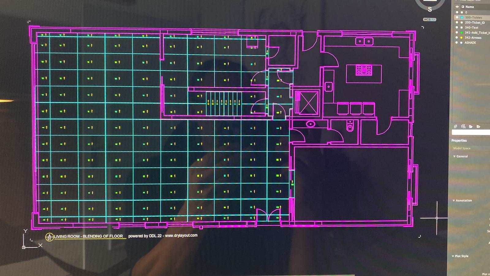
What Changes on the Shop Floor
Approval Workflow Instead of Phone Calls and Emails
Without a digital workflow: the architect comes to the fabrication shop, reviews physical slabs, and approves by phone or email. Information gets lost. Three weeks later, no one can say with certainty which areas were actually approved. With the workflow: the architect views the digital blending online and approves with a timestamp. The freeze mechanism prevents retroactive changes. And when 16 specially cut pieces break on site due to an accident — a real case from an international project — replacement stones can be planned overnight, cut the next day, and if needed airfreighted to the site within days. Both the exact cut data and the visual appearance of surrounding pieces are already in the system — so the new parts can be blended in for matching color and Veining and recut accordingly. All information remains available for any repairs or replacements needed later — similar to a BIM model. Lasa Marmo reports 20 percent cost savings through this workflow.
Errors That Never Reach the Cutting Machine
The typical failure points with manual dimension transfer: wrong thickness assigned because the plan was misread. A slab was cut that didn't fall within the approved range — expensive material destroyed. Edge finishing overlooked, rework required. In the digital workflow, all information is encoded in the layers and validated before the CNC export. Three automatically generated report types give project managers the ability to deliver key information quickly to decision-makers — while simultaneously passing 100 percent reliable detail data to those working with the materials behind the scenes and responsible for quality assurance.
Remnants That Don't Disappear
Every cut leaves remnants. Without tracking, these pieces end up in the warehouse unidentified. After a few months — or sometimes years — they get discarded. With digital tracking: the remnant gets a barcode linked to a photo and exact dimensions. The next project searches available remnant stock first — before opening a new slab. Granimor in Switzerland, for example, uses a handheld scanner daily — not just for remnant utilization, but also for inventory management.

Nesting Solves a Placement Problem. Project Planning Solves a Business Problem.
The digital DXF workflow makes traditional nesting redundant — because it's handled automatically in the background within the Blending step. In the future, AI tools will simplify this further. What emerges beyond that is substantial: Which slab belongs to which project? Which approval is in place? What does the job actually cost? What remnant material is available? All of this is answered within a single continuous digital workflow — from architect plan to CNC export, with full traceability down to the last off-cut.
A natural stone project spans months and involves architects, designers, contractors, and fabrication shops — often across multiple countries. The digital workflow creates a continuous thread connecting all stakeholders: transparent, documented, and with measurable results.
DXF is an internationally established CAD data format that every drawing application can export and every fabrication machine can read. The DXF interface doesn't stand in the way of adopting the digital workflow — regardless of which software a shop currently uses.
When yield increases from 50 to 75 or 80 percent, the investment pays for itself within the first few weeks.
Questions about digital job preparation? Jan Keller has answers.
Related reading: Stone Waste in the Fabrication Shop — Slab Offcuts as Dead Weight or Revenue Opportunity?
Explore DDL Solutions
Ready to Test Digital Job Preparation?
Jan Keller shows how the DXF workflow works in a fabrication shop — from importing the architect's drawing to exporting for CNC.